Файл:Epicyclic Gearing Stationary Sun.gif
Перейти к навигации
Перейти к поиску
Нет версии с бо́льшим разрешением.
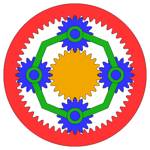
Epicyclic_Gearing_Stationary_Sun.gif (500 × 500 пкс, размер файла: 2,66 МБ, MIME-тип: image/gif, закольцованный, 170 фреймов, 6,8 с)
Примечание: По техническим причинам миниатюры подобных GIF-изображений высокого разрешения не анимируются.

|
Существует векторная версия этого изображения. Её следует использовать, если качество её не хуже, чем эта растровая версия.
File:Epicyclic Gearing Stationary Sun.gif → File:Epicyclic Gearing Stationary Sun.svg
Подробнее о векторной графике в статье «Перевод изображений в формат SVG». Также доступна информация о поддержке формата SVG в MediaWiki. |
 |
Краткое описание
| Описание |
Deutsch: Umlaufrädergetriebe; Zähne: zSonne=24, zPlaneten=16, zHohl=56.
English: Epicyclic gearing; Teeth: zsun=24, zplanet=16, zring=56. |
| Дата | |
| Источник | Собственная работа |
| Автор | Jahobr |
| Другие версии |
|
| GIF‑разработка | |
| Исходный код | MATLAB codefunction Epicyclic_Gearing()
% Source code for drawing epicyclic gearing.
% The shape of the gears is not precise, it creates a decent GIF and a SVG.
%
% 2017-01-22 Jahobr
teethSun = 24; % if divisible by 4 plotting is easier
teethPlan = 16; % if divisible by 4 plotting is easier
teethRing = teethSun+teethPlan*2;
modul = 16;
carrierCol = round([0.1 0.7 0.1].*255)./255; % green
sunCol = round([0.95 0.65 0 ].*255)./255; % yellow (obviously)
palnetCol = round([0.2 0.2 1 ].*255)./255; % blue (obviously)
ringCol = round([1 0.2 0.2].*255)./255; % red
diameterSun = modul.*teethSun;
diameterPlan = modul.*teethPlan;
diameterCarr = diameterSun+diameterPlan;
diameterRing = diameterSun+diameterPlan+diameterPlan;
nPlan = 4; % number of planets
xySize = 500; % size in pixel
scaleReduction = 2; % the size reduction: adds antialiasing
[pathstr,fname] = fileparts(which(mfilename)); % save files under the same name and at file location
figHandle = figure(15674455); clf
set(figHandle,'Units','pixel');
set(figHandle,'ToolBar','none');
set(figHandle,'GraphicsSmoothing','on') % requires at least version 2014b
set(figHandle,'position',[1 1 [xySize xySize]*scaleReduction]); % big start image for antialiasing later [x y width height]
axesHandle = axes;
hold(axesHandle,'on')
set(axesHandle,'position',[-0.05 -0.05 1.1 1.1]); % stretch axis bigger as figure, easy way to get rid of ticks [x y width height]
xlim([-diameterRing*0.72 diameterRing*0.72]);
ylim([-diameterRing*0.72 diameterRing*0.72]);
axis equal; drawnow;
for currentCase = 1:4;
switch currentCase
case 1 % Stationary_Sun
nFrames = 170;
reducedRGBimage = uint8(ones(xySize,xySize,3,nFrames)); % allocate
angleCarrier = -linspace(0,pi*2/nPlan,nFrames+1); % define gear position in frames
angleCarrier = angleCarrier(1:end-1); % remove last frame, it would be double
anglePlan = angleCarrier.*( teethSun/teethPlan+1 ); % gear ratio
anglePlan = anglePlan + (pi/teethPlan); % ALLIGNMENT; THIS MAY NEED MANUAL ADJUSTMENT
angleRing = angleCarrier.* (teethSun+teethRing) / teethRing; % gear ratio
angleRing = angleRing + 0; % ALLIGNMENT; THIS MAY NEED MANUAL ADJUSTMENT
angleSun = zeros(size(anglePlan));
saveName = [fname '_Stationary_Sun'];
case 2 % Stationary_Ring
nFrames = 170;
reducedRGBimage = uint8(ones(xySize,xySize,3,nFrames)); % allocate
angleCarrier = -linspace(0,pi*2/nPlan,nFrames+1); % define gear position in frames
angleCarrier = angleCarrier(1:end-1); % remove last frame, it would be double
anglePlan = angleCarrier.*( teethSun/teethPlan+1 ); % gear ratio
anglePlan = -anglePlan + (pi/teethPlan); % ALLIGNMENT; THIS MAY NEED MANUAL ADJUSTMENT
angleSun = angleCarrier.* (1+teethRing/teethSun); % gear ratio
angleSun = angleSun + 0; % ALLIGNMENT; THIS MAY NEED MANUAL ADJUSTMENT
angleRing = zeros(size(anglePlan));
saveName = [fname '_Stationary_Ring'];
case 3 % Stationary_Carrier
nFrames = 20;
reducedRGBimage = uint8(ones(xySize,xySize,3,nFrames)); % allocate
angleSun = -linspace(0,pi*2/teethSun,nFrames+1); % define gear position in frames
angleRing = -angleSun.* (teethSun/teethRing); % gear ratio
angleRing = angleRing + 0; % ALLIGNMENT; THIS MAY NEED MANUAL ADJUSTMENT
anglePlan = angleSun.* (teethSun/teethPlan ); % gear ratio
anglePlan = -anglePlan + (pi/teethPlan); % ALLIGNMENT; THIS MAY NEED MANUAL ADJUSTMENT
angleCarrier = zeros(size(anglePlan));
saveName = [fname '_Stationary_Carrier'];
case 4 % Direct_Drive
nFrames = 170;
reducedRGBimage = uint8(ones(xySize,xySize,3,nFrames)); % allocate
angleAll = -linspace(0,pi*2/nPlan,nFrames+1); % define gear position in frames
angleAll = angleAll(1:end-1); % remove last frame, it would be double
angleCarrier = angleAll;
angleCarrier = angleCarrier + 0; % ALLIGNMENT; THIS MAY NEED MANUAL ADJUSTMENT
anglePlan = angleAll;
anglePlan = anglePlan + (pi/teethPlan); % ALLIGNMENT; THIS MAY NEED MANUAL ADJUSTMENT
angleRing = angleAll;
angleRing = angleRing + 0; % ALLIGNMENT; THIS MAY NEED MANUAL ADJUSTMENT
angleSun = angleAll;
saveName = [fname '_Direct_Drive'];
end
for iFrame = 1:nFrames
cla(axesHandle) % fresh frame
%% ring
drawRingGear(axesHandle,teethRing,modul,ringCol,angleRing(iFrame))
%% sun
drawCogWheel(axesHandle,[0 0],teethSun ,modul,sunCol,angleSun(iFrame));
%% planets
angPlan = linspace(0,2*pi,nPlan+1);
angPlan = angPlan(1:end-1);
for iPlan = angPlan
[X,Y] = pol2cart(iPlan+angleCarrier(iFrame) ,diameterCarr/2);
drawCogWheel(axesHandle,[X,Y],teethPlan,modul,palnetCol,anglePlan(iFrame)); % planetary gear
end
%% carrier
angCarr= linspace(0,2*pi,nPlan*2+1);
[X,Y] = pol2cart([angCarr fliplr(angCarr)]+angleCarrier(iFrame) ,[ones(size(angCarr))*diameterCarr/2.05 ones(size(angCarr))* diameterCarr/1.75]);
patch(X,Y,carrierCol,'EdgeColor',[0 0 0],'LineWidth',1.5) % full outer disc
for iPlan = angPlan
[X,Y] = pol2cart(iPlan+angleCarrier(iFrame) ,diameterCarr/2);
circlePatch(X,Y,diameterPlan*0.25,carrierCol,1.5);
circlePatch(X,Y,diameterPlan*0.15,palnetCol,1.5);
end
%% save animation
f = getframe(figHandle);
reducedRGBimage(:,:,:,iFrame) = imReduceSize(f.cdata,scaleReduction); % the size reduction: adds antialiasing
if iFrame == 1 % SVG
if ~isempty(which('plot2svg'))
plot2svg(fullfile(pathstr, [fname '_Stationary.svg']),figHandle) % by Juerg Schwizer
else
disp('plot2svg.m not available; see http://www.zhinst.com/blogs/schwizer/');
end
end
end
map = createImMap(reducedRGBimage,16,[0 0 0;1 1 1;carrierCol;sunCol;palnetCol;ringCol]); % colormap
im = uint8(ones(xySize,xySize,1,nFrames)); % allocate
for iFrame = 1:nFrames
im(:,:,1,iFrame) = rgb2ind(reducedRGBimage(:,:,:,iFrame),map,'nodither');
end
imwrite(im,map,fullfile(pathstr, [saveName '.gif']),'DelayTime',1/25,'LoopCount',inf) % save gif
disp([saveName '.gif has ' num2str(numel(im)/10^6 ,4) ' Megapixels']) % Category:Animated GIF files exceeding the 50 MP limit
end
function drawCogWheel(axesHandle,center,toothNumber,modul,colFilling,startOffset)
% DRAWTOOTHEDWHEEL - draw a simple Toothed Wheel
%
% Input:
% axesHandle:
% center: [x y]
% toothNumber: scalar
% modul: scalar tooth "size"
% colFilling: color of filling [r g b]
% startOffset: start rotation (scalar)[rad]
effectiveRadius = modul*toothNumber/2; % effective effectiveRadius
outsideRadius = effectiveRadius+1* modul; % +---+ +---+
upperRisingRadius = effectiveRadius+0.5*modul; % / \ / \
% effective Radius % / \ / \
lowerRisingRadius = effectiveRadius-0.5*modul; % I I I I
rootRadius = effectiveRadius-1.1*modul; % + - - - + + - - - + +
angleBetweenTeeth = 2*pi/toothNumber; % angle between 2 teeth
angleOffPoints = (0:angleBetweenTeeth/16:(2*pi));
angleOffPoints = angleOffPoints+startOffset; % apply rotation offset
angleOffPoints( 7:16:end) = angleOffPoints( 7:16:end) + 1/toothNumber^1.2; % hack to create smaller tooth tip
angleOffPoints(11:16:end) = angleOffPoints(11:16:end) - 1/toothNumber^1.2; % hack to create smaller tooth tip
angleOffPoints( 8:16:end) = (angleOffPoints( 7:16:end) + angleOffPoints(9:16:end))/2; % shift the neighbouring tip point in accordingly
angleOffPoints(10:16:end) = (angleOffPoints(11:16:end) + angleOffPoints(9:16:end))/2; % shift the neighbouring tip point in accordingly
angleOffPoints( 6:16:end) = angleOffPoints( 6:16:end) + 1/toothNumber^1.7; % hack to create slender tooth
angleOffPoints(12:16:end) = angleOffPoints(12:16:end) - 1/toothNumber^1.7; % hack to create slender tooth
radiusOffPoints = angleOffPoints; % allocate with correct site
radiusOffPoints(1:16:end) = rootRadius; % center bottom I
radiusOffPoints(2:16:end) = rootRadius; % left bottom I
radiusOffPoints(3:16:end) = rootRadius; % left bottom corner +
radiusOffPoints(4:16:end) = lowerRisingRadius; % lower rising bottom \
radiusOffPoints(5:16:end) = effectiveRadius; % rising edge \
radiusOffPoints(6:16:end) = upperRisingRadius; % upper rising edge \
radiusOffPoints(7:16:end) = outsideRadius; % right top corner +
radiusOffPoints(8:16:end) = outsideRadius; % right top I
radiusOffPoints(9:16:end) = outsideRadius; % center top I
radiusOffPoints(10:16:end) = outsideRadius; % left top I
radiusOffPoints(11:16:end) = outsideRadius; % left top corner +
radiusOffPoints(12:16:end) = upperRisingRadius; % upper falling edge /
radiusOffPoints(13:16:end) = effectiveRadius; % falling edge /
radiusOffPoints(14:16:end) = lowerRisingRadius; % lower falling edge /
radiusOffPoints(15:16:end) = rootRadius; % right bottom corner +
radiusOffPoints(16:16:end) = rootRadius; % right bottom I
[X,Y] = pol2cart(angleOffPoints,radiusOffPoints);
X = X+center(1); % center offset
Y = Y+center(2); % center offset
patch(X,Y,colFilling,'EdgeColor',[0 0 0],'LineWidth',1.5)
% plot(axesHandle,X,Y,'-x','linewidth',2,'color',[0 0 0]);
% %% effective Radius
% [X,Y] = pol2cart(angleOffPoints,effectiveRadius);
% X = X+center(1); % center offset
% Y = Y+center(2); % center offset
% plot(axesHandle,X,Y,'-.','color',[0 0 0]);
function drawRingGear(axesHandle,toothNumber,modul,colFilling,startOffset)
% subfunction for the outer static gear
effectiveRadius = modul*toothNumber/2; % effective effectiveRadius
outsideRadius = effectiveRadius-1* modul; % +---+ +---+
upperRisingRadius = effectiveRadius-0.5*modul; % / \ / \
% effective Radius % / \ / \
lowerRisingRadius = effectiveRadius+0.5*modul; % I I I I
rootRadius = effectiveRadius+1.1*modul; % + - - - + + - - - + +
angleBetweenTeeth = 2*pi/toothNumber; % angle between 2 teeth
angleOffPoints = (0:angleBetweenTeeth/16:(2*pi));
angleOffPoints = angleOffPoints+startOffset; % apply rotation offset
%% outerEdge
maxRadius = rootRadius*1.2; % definition of outer line
[X,Y] = pol2cart(angleOffPoints,maxRadius);
patch(X,Y,colFilling,'EdgeColor',[0 0 0],'LineWidth',1.5) % full outer disc
% plot(axesHandle,X,Y,'linewidth',2,'color',[0 0 0]); % draw outer circle
%% inner teeth
radiusOffPoints = angleOffPoints; % init
angleOffPoints(7:16:end) = angleOffPoints(7:16:end) + 1/toothNumber^1.2; % hack to create smaller tooth tip
angleOffPoints(11:16:end) = angleOffPoints(11:16:end) - 1/toothNumber^1.2; % hack to create smaller tooth tip
angleOffPoints(8:16:end) = (angleOffPoints(7:16:end) + angleOffPoints(9:16:end))/2; % shift the neighbouring tip point in accordingly
angleOffPoints(10:16:end) = (angleOffPoints(11:16:end) + angleOffPoints(9:16:end))/2; % shift the neighbouring tip point in accordingly
angleOffPoints(6:16:end) = angleOffPoints(6:16:end) + 1/toothNumber^1.7; % hack to create slender tooth
angleOffPoints(12:16:end) = angleOffPoints(12:16:end) - 1/toothNumber^1.7; % hack to create slender tooth
radiusOffPoints(1:16:end) = rootRadius; % center bottom I
radiusOffPoints(2:16:end) = rootRadius; % left bottom I
radiusOffPoints(3:16:end) = rootRadius; % left bottom corner +
radiusOffPoints(4:16:end) = lowerRisingRadius; % lower rising bottom \
radiusOffPoints(5:16:end) = effectiveRadius; % rising edge \
radiusOffPoints(6:16:end) = upperRisingRadius; % upper rising edge \
radiusOffPoints(7:16:end) = outsideRadius; % right top corner +
radiusOffPoints(8:16:end) = outsideRadius; % right top I
radiusOffPoints(9:16:end) = outsideRadius; % center top I
radiusOffPoints(10:16:end) = outsideRadius; % left top I
radiusOffPoints(11:16:end) = outsideRadius; % left top corner +
radiusOffPoints(12:16:end) = upperRisingRadius; % upper falling edge /
radiusOffPoints(13:16:end) = effectiveRadius; % falling edge /
radiusOffPoints(14:16:end) = lowerRisingRadius; % lower falling edge /
radiusOffPoints(15:16:end) = rootRadius; % right bottom corner +
radiusOffPoints(16:16:end) = rootRadius; % right bottom I
[X,Y] = pol2cart(angleOffPoints,radiusOffPoints);
patch(X,Y,[1 1 1],'EdgeColor',[0 0 0],'LineWidth',1.5) % overlay white area for inner teeth
% plot(axesHandle,X,Y,'-','linewidth',2,'color',[0 0 0]); % teeth line
function circlePatch(x,y,r,col,linW)
% x coordinates of the center
% y coordinates of the center
% r is the radius of the circle
% col patch color
% linW LineWidth
angleOffPoints = linspace(0,2.001*pi,200);
xc = x + r*cos(angleOffPoints);
yc = y + r*sin(angleOffPoints);
patch(xc,yc,col,'EdgeColor',[0 0 0],'LineWidth',linW);
function im = imReduceSize(im,redSize)
% Input:
% im: image, [imRows x imColumns x nChannel x nStack] (unit8)
% imRows, imColumns: must be divisible by redSize
% nChannel: usually 3 (RGB) or 1 (grey)
% nStack: number of stacked images
% usually 1; >1 for animations
% redSize: 2 = half the size (quarter of pixels)
% 3 = third the size (ninth of pixels)
% ... and so on
% Output:
% imNew: unit8([imRows/redSize x imColumns/redSize x nChannel x nStack])
%
% an alternative is : imNew = imresize(im,1/reduceImage,'bilinear');
% BUT 'bicubic' & 'bilinear' produces fuzzy lines
% IMHO this function produces nicer results as "imresize"
[nRow,nCol,nChannel,nStack] = size(im);
if redSize==1; return; end % nothing to do
if redSize~=round(abs(redSize)); error('"redSize" must be a positive integer'); end
if rem(nRow,redSize)~=0; error('number of pixel-rows must be a multiple of "redSize"'); end
if rem(nCol,redSize)~=0; error('number of pixel-columns must be a multiple of "redSize"'); end
nRowNew = nRow/redSize;
nColNew = nCol/redSize;
im = double(im).^2; % brightness rescaling from "linear to the human eye" to the "physics domain"; see youtube: /watch?v=LKnqECcg6Gw
im = reshape(im, nRow, redSize, nColNew*nChannel*nStack); % packets of width redSize, as columns next to each other
im = sum(im,2); % sum in all rows. Size of result: [nRow, 1, nColNew*nChannel]
im = permute(im, [3,1,2,4]); % move singleton-dimension-2 to dimension-3; transpose image. Size of result: [nColNew*nChannel, nRow, 1]
im = reshape(im, nColNew*nChannel*nStack, redSize, nRowNew); % packets of width redSize, as columns next to each other
im = sum(im,2); % sum in all rows. Size of result: [nColNew*nChannel, 1, nRowNew]
im = permute(im, [3,1,2,4]); % move singleton-dimension-2 to dimension-3; transpose image back. Size of result: [nRowNew, nColNew*nChannel, 1]
im = reshape(im, nRowNew, nColNew, nChannel, nStack); % putting all channels (rgb) back behind each other in the third dimension
im = uint8(sqrt(im./redSize^2)); % mean; re-normalize brightness: "scale linear to the human eye"; back in uint8
function map = createImMap(imRGB,nCol,startMap)
% createImMap creates a color-map including predefined colors.
% "rgb2ind" creates a map but there is no option to predefine some colors,
% and it does not handle stacked images.
% Input:
% imRGB: image, [imRows x imColumns x 3(RGB) x nStack] (unit8)
% nCol: total number of colors the map should have, [integer]
% startMap: predefined colors; colormap format, [p x 3] (double)
imRGB = permute(imRGB,[1 2 4 3]); % step1; make unified column-image (handling possible nStack)
imRGBcolumn = reshape(imRGB,[],1,3,1); % step2; make unified column-image
fullMap = double(permute(imRGBcolumn,[1 3 2]))./255; % "column image" to color map
[fullMap,~,imMapColumn] = unique(fullMap,'rows'); % find all unique colores; create indexed colormap-image
% "cmunique" could be used but is buggy and inconvenient because the output changes between "uint8" and "double"
nColFul = size(fullMap,1);
nColStart = size(startMap,1);
disp(['Number of colors: ' num2str(nColFul) ' (including ' num2str(nColStart) ' self defined)']);
if nCol<=nColStart; error('Not enough colors'); end
if nCol>nColFul; warning('More colors than needed'); end
isPreDefCol = false(size(imMapColumn)); % init
for iCol = 1:nColStart
diff = sum(abs(fullMap-repmat(startMap(iCol,:),nColFul,1)),2); % difference between a predefined and all colores
[mDiff,index] = min(diff); % find matching (or most similar) color
if mDiff>0.05 % color handling is not precise
warning(['Predefined color ' num2str(iCol) ' does not appear in image'])
continue
end
isThisPreDefCol = imMapColumn==index; % find all pixel with predefined color
disp([num2str(sum(isThisPreDefCol(:))) ' pixel have predefined color ' num2str(iCol)]);
isPreDefCol = or(isPreDefCol,isThisPreDefCol); % combine with overall list
end
[~,mapAdditional] = rgb2ind(imRGBcolumn(~isPreDefCol,:,:),nCol-nColStart,'nodither'); % create map of remaining colors
map = [startMap;mapAdditional];
|


Лицензирование
Я, владелец авторских прав на это произведение, добровольно публикую его на условиях следующей лицензии:
| Этот файл доступен на условиях Creative Commons CC0 1.0 Универсальной передачи в общественное достояние (Universal Public Domain Dedication). | |
| Лица, связанные с работой над этим произведением, решили передать данное произведение в общественное достояние, отказавшись от всех прав на произведение по всему миру в рамках закона об авторских правах (а также связанных и смежных прав), в той степени, которую допускает закон. Вы можете копировать, изменять, распространять и исполнять данное произведение в любых целях, в том числе в коммерческих, без получения на это разрешения автора.
|
История файла
Нажмите на дату/время, чтобы увидеть версию файла от того времени.
| Дата/время | Миниатюра | Размеры | Участник | Примечание | |
|---|---|---|---|---|---|
| текущий | 23:34, 29 октября 2017 | | 500 × 500 (2,66 МБ) | wikimediacommons>Jahobr | graph smoothing |
Использование файла
Следующие 2 страницы используют этот файл: