Файл:Hertz Transmitter Receiver.svg
Перейти к навигации
Перейти к поиску

Размер этого PNG-превью для исходного SVG-файла: 776 × 600 пкс. Другие разрешения: 311 × 240 пкс | 621 × 480 пкс | 994 × 768 пкс | 1280 × 989 пкс | 2560 × 1978 пкс | 990 × 765 пкс.
Исходный файл (SVG-файл, номинально 990 × 765 пкс, размер файла: 35 КБ)
Краткое описание
| Описание |
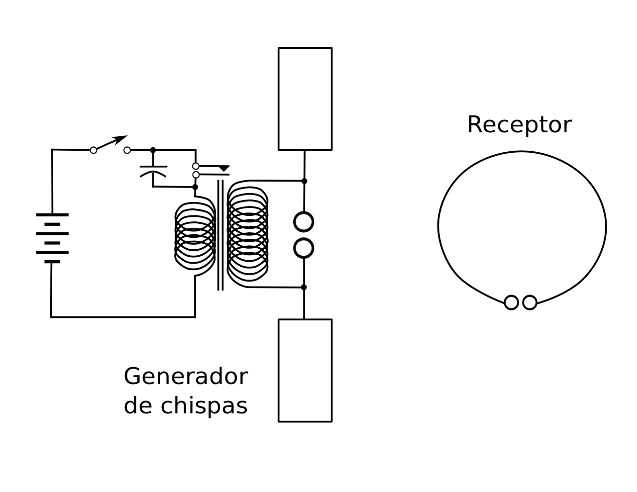
English: Experimental circuit used by Heinrich Hertz in 1887 to discover the existence of radio waves. It is a spark gap radio transmitter (left) consisting of a dipole antenna made of two horizontal wires with metal plates on the ends to add capacitance, with a spark gap between them, attached to an induction coil powered by a battery. Pulses of high voltage applied to the antenna by the induction coil cause sparks across the spark gap, which excite standing waves of current in the antenna, causing it to radiate electromagnetic waves (radio waves). The waves were detected by a crude receiver consisting of a resonant loop antenna (right) made of a circle of wire, with a micrometer spark gap between its ends. The device actually produced single short pulses of radio waves; when Hertz pushed the switch in the primary circuit of the coil, a single spark would jump across the transmitting antenna, creating a radio wave pulse that would induce a single tiny spark in the receiver loop. The frequency of the waves was determined by the length of the antenna; the short antennas Hertz used produced high frequency waves in the UHF band, about the frequency of modern television transmitters. |
| Дата | |
| Источник | Собственная работа |
| Автор | DMGualtieri |
Лицензирование
Я, владелец авторских прав на это произведение, добровольно публикую его на условиях следующей лицензии:
Этот файл доступен по лицензии Creative Commons Attribution-Share Alike 3.0 Unported.
- Вы можете свободно:
- делиться произведением – копировать, распространять и передавать данное произведение
- создавать производные – переделывать данное произведение
- При соблюдении следующих условий:
- атрибуция – Вы должны указать авторство, предоставить ссылку на лицензию и указать, внёс ли автор какие-либо изменения. Это можно сделать любым разумным способом, но не создавая впечатление, что лицензиат поддерживает вас или использование вами данного произведения.
- распространение на тех же условиях – Если вы изменяете, преобразуете или создаёте иное произведение на основе данного, то обязаны использовать лицензию исходного произведения или лицензию, совместимую с исходной.
История файла
Нажмите на дату/время, чтобы увидеть версию файла от того времени.
| Дата/время | Миниатюра | Размеры | Участник | Примечание | |
|---|---|---|---|---|---|
| текущий | 09:54, 8 ноября 2014 | | 990 × 765 (35 КБ) | wikimediacommons>FJGAR (BIS) | Traducción al castellano |
Использование файла
Следующая страница использует этот файл: