Файл:Optical flat interference.svg
Перейти к навигации
Перейти к поиску

Размер этого PNG-превью для исходного SVG-файла: 715 × 599 пкс. Другие разрешения: 286 × 240 пкс | 573 × 480 пкс | 916 × 768 пкс | 1221 × 1024 пкс | 2443 × 2048 пкс | 1417 × 1188 пкс.
Исходный файл (SVG-файл, номинально 1417 × 1188 пкс, размер файла: 48 КБ)
Краткое описание
| Описание |
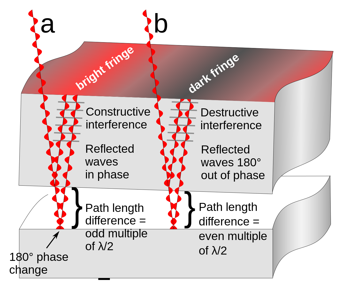
English: Diagram showing how interference fringes are created by an optical flat. The upper object is a section of a glass optical flat resting on another flat reflective surface. Light rays (red) from a monochromatic light source pass through the flat and reflect from both the bottom surface of the glass and the surface it is resting on. Since there is a tiny gap between the two surfaces, the ray reflecting off the bottom surface travels a greater distance than the top ray. It also experiences a 180° phase change at the reflection from the bottom plate (the reflection from the top plate causes no phase change). The parallel rays superpose. At locations (a) where the extra distance travelled by the 2nd ray (twice the width of the gap) is equal to an even multiple of a half-wavelength (λ/2) of the light the two reflected waves will be in phase and will add, reinforcing each other, resulting in a bright reflected ray. This is called constructive interference. At other locations (b) the path difference between the rays is equal to an odd multiple of λ/2, so the reflected waves are 180° out of phase. They subtract, canceling each other out, resulting in little or no reflected light. This is called destructive interference.
When the two surfaces are not parallel, as in the diagram, this results in a pattern of alternating bright and dark bands visible on the surface, called interference fringes. Two adjacent interference fringes represent a difference in height of the surface of one-half wavelength of the light used, so interference patterns can be used to measure the flatness of surfaces to millionths of an inch. In this diagram the width of the gap and the wavelength of the light waves is greatly exaggerated; light has wavelengths around 10-7 meter.Русский: Интерференция в тонком воздушном клине |
| Дата | |
| Источник | Собственная работа |
| Автор | Chetvorno |
| Другие версии |
|
| SVG‑разработка |


Лицензирование
Я, владелец авторских прав на это произведение, добровольно публикую его на условиях следующей лицензии:
| Этот файл доступен на условиях Creative Commons CC0 1.0 Универсальной передачи в общественное достояние (Universal Public Domain Dedication). | |
| Лица, связанные с работой над этим произведением, решили передать данное произведение в общественное достояние, отказавшись от всех прав на произведение по всему миру в рамках закона об авторских правах (а также связанных и смежных прав), в той степени, которую допускает закон. Вы можете копировать, изменять, распространять и исполнять данное произведение в любых целях, в том числе в коммерческих, без получения на это разрешения автора.
|
История файла
Нажмите на дату/время, чтобы увидеть версию файла от того времени.
| Дата/время | Миниатюра | Размеры | Участник | Примечание | |
|---|---|---|---|---|---|
| текущий | 16:45, 16 января 2022 | | 1417 × 1188 (48 КБ) | wikimediacommons>Aiden1123 | Reverted to version as of 03:54, 9 May 2017 (UTC) |
Использование файла
Следующая страница использует этот файл: